Table of Contents
Paged moved
IPSPi1Hb: Raspberry Pi Internet Power Switch
An Internet Power Switch (IPS) has been built for Mt Pleasant. Its main purpose is to provide remote and local control of power to a small cluster in the computer room. This can be operated from the front panel of the device or remotely via a terminal window. There are also several Remote Switches which plug into a wall socket and allow remote control of a single device via WiFi. Software on the IPS allows for control of these devices.
IPS Usage
Current configuration of ipspi1Hb
| PS1 | PS2 | PS3 | PS4 | PS5 | PS6 | PS7 |
| FlexbuffHb 1 | Universal counter | Laser PSU | - | FlexbuffHb 2 | External PS | External PS |
External PS: External Power supply provide current to the two RF to Optics + RF filters. We need two since a 5 and a 12 Volts are required.
dbbc3 is powered up directly from a separate UPS. We don't want to overload the system.
Local control
The front panel of the IPS consists of an Enable button and one button to control each of the 7 connected devices. There is a LED in each control button that indicates if power is on to the device. To avoid accidental toggling, the Enable button must be held on when controlling power to a device and released between button presses.
To turn power on/off to a device, hold down Enable and then press the button for the device you want to control.
Software/remote control
The Raspberry Pi PC in the IPS can be accessed via VNC or on a terminal with ssh. The password is the usual one.
- VNC to ipspi1hb and start the Switch Interface app on the desktop, or…
- ssh pi@ipspi1hb and type
SwitchInterface.py
This starts a command-line interface that allows you to control power to devices. Type 'help' for a list of possible commands and 'help <command name>' for specific help on a command.
- To get current status of devices:
status
- To turn a device on:
on <device number>
- To turn a device off:
off <device number>
- To turn a device off and on again. This turns the device off, waits 15 sec, then turns it on again
reboot <device number>
- Disable a device. This prevents switching of a device from the panel or from software. i.e. if you really don't want the device played with.
disable <device number>
- Enable a device
enable <device number>
- Name a device. The status display shows a short description of the attached device which you can change:
name <device number> <text>. e.gname 3 My computer
Remote Switch Usage
These are small power-socket mounted switches for remote control of whatever device is plugged into them. Once set up, the switch can be controlled locally via a button or remotely from the IPS via the Switch Interface software. The switches share information about their state with some server software on the IPS and can receive remote commands from the IPS too. Because the switches are designed to use the WiFi network intermittently, they check in with the server at regular (configurable) intervals to synchronise state information and process any pending commands. If a device is turned on or off locally after a remote (software) command has been sent, then the local operation takes precedence. Likewise, if the remote command is the most recent, it is executed at the next check-in.
The switches operate in two modes: setup and operating.
When turned on, the Switch will look for the WiFi network it was previously configured for and try to connect. The busy LED (orange) will flash and so will the WiFi LED (red). If it was not configured, or could not connect, it will start up as a WiFi access point which you can connect to and configure the switch (see below). This is indicated by a flashing busy LED and a solid WiFi LED.
If you hold down the button when you turn on the switch, it will enter setup mode regardless of the previous state. This is useful if you need to reconfigure the device. Hold down the button until you see the Busy LED (orange) flashing and the WiFi LED (red) on.
Wifi Modes
To keep RFI down, the switch can be configured to only turn its WiFi on when it does an update. To toggle between these modes, either hold down the button on the switch for more than 2 seconds or set the update interval in the SwitchInterface software to 0.
Intermittent WiFi
In this mode, the WiFi is off most of the time but the switch will connect at a specified time interval and do an update. This update interval can be configured in setup mode or via the SwitchInterface program.
Constant WiFi
In this mode, the WiFi is on all the time and the switch will attempt a status update with the server every 60s (by default) or whatever update time is specified when in setup mode. This is indicated by the WiFi LED being on at all times.
Setup mode
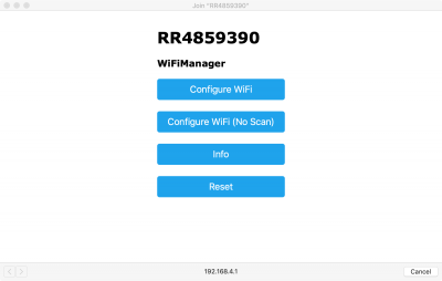
In setup mode, the switch configures itself as a WiFi access point with SSID “RR” followed by a string of numbers (e.g. RR4859390) which is the chip ID on the microcontroller. Connect to that network from a WiFi enabled device and you can configure the switch.
Once you've connected, you will see a new window like this on your browser:
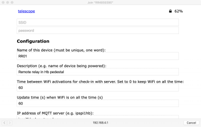
Choose “Configure WiFi”. You'll then see something like this:
Select the network you want the switch to connect to from the list at the top of the screen and put in the WiFi password. Make any other configuration changes here too. NOTE: the Name of the switch, the address of the MQTT server (ipspi1hb in Hobart) and the update time when WiFi is constantly on (see below) can only be configured from this interface. Other items are remotely configurable from the SwitchInterface software.
Operating modes
The switch may be operated either locally or remotely.
Local operation
The switch can be controlled locally using the button on the top. A short press of the button will turn the attached device on or off (indicated by the green LED) and a long press will put the switch in or out of its constant WiFi mode (indicated by the red LED). Holding down the button when you turn it on will put the device into setup mode.
Remote (software) control
Connect to ipspi1hb via VNC or ssh as above and start the Switch Interface. The status command gives the status of all known remote switches. Each device has a short name rather than a number, e.g. RR01, and this is the label to use when controlling it. A longer description of the device can be given with the remote_description command and this will be displayed in the status output.
The remote switch checks in with the IPS PC regularly. The interval between checks is configurable via the remote_interval command. To turn the attached device on, off, or to reboot it, use the remote_on, remote_off or remote_reboot commands respectively. The command will remain pending until the device checks in, when it will be executed. If however, the device is turned on or off locally after the command is issued, it will be ignored.
Hardware and Software
Hardware consists of a Raspberry Pi PC inside the IPS, connected to two relay boards for managing power switching and a custom-made circuit board primarily for managing input from front-panel buttons and displaying switch status on the panel.
Software running on the Raspberry Pi consists of four programs:
- A front-end program,
SwitchInterface.py, runs from a terminal window. Multiple instances can be run at once. It provides a user interface for monitoring and control of the rack-mounted IPS and all available Remote Switches. - Behind this is
RemoteRelayServer.pywhich runs a MQTT server and manages input from buttons on the front panel of the IPS. The MQTT server accepts requests fromSwitchInterface.pyand from the Remote Switches. The Remote Switches are designed to have their WiFi switched off for most of the time to keep radio interference to a minimum, but report in once per minute (or at another configurable interval).RemoteRelayServer.pymanages requests to switch this device and sends any update commands to the Remote Switch whenever it checks in on the network. RemoteRelayServer.pyInteracts with the hardware in the rack-mounted IPS. It takes commands via MQTT from RemoteSelayServer.py and actually switches the corresponding relay. It also controls the LEDs that indicate status of the switches. The circuit board also has three temperature and humidity sensors attached and this software logs their values every minute to a SQL database.IPSTHServer.pyprovides temperature and humidity data to MONICA on request
The Remote Switches have Arduino-compatible ESP8266 NodeMCU microcontrollers to manage a single relay switch. Each microcontroller runs software to manage the relay, WiFi connection, MQTT communication, a local button and some LEDs. When powered on it will connect to the local WiFi network if configured or start up as an access point if not, allowing a local connection for initial configuration (which is saved to non-volatile memory for next time). The software is in the Arduino directory, called RelayControl.ino.

