
User Tools
Sidebar
This wiki is not maintained! Do not use this when setting up AuScope experiments!
Table of Contents
Hardware setup and configuration
Katherine is set up with a different set of temperature and humidity sensors to the other two sites (DHT11 compared to DHT22). The Raspberry Pi in the maser room also has an Arduino board attached to it for the accelerometer and some analog temperature sensors.
Katherine
Connect the Raspberry Pi to the Arduino via a USB cable. The Arduino will get power via the cable but it's a good idea to also give the Arduino power via a DC power supply as this provides a more stable reference voltage for the analog sensors.
DHT11 temperature and humidity sensors
Each DHT11 sensor requires 3.3 - 5V, ground and a digital input pin. Pinouts are shown below:
 Use any 5V and GND pin from the RPi.
Any of the RPi digital pins should be fine to use. That’s the ones labeled BCM here: Raspberry Pi pinouts

IR transmitters, receivers
These have three pins as well:
pin    connection
---    ---------------
-      GND
middle +5V
S      digital signal
Connect them to the Raspberry Pi. Any GND or +5V pin will be fine.
Use any digital pin on the Pi and make sure they are set to “False” in TempHumid.conf (you can give them an appropriate label though). See below.
Accelerometer
This should be connected to the Arduino:
module pin    Arduino connection
----------    ---------------
VCC           +5V
X out         A0
Y out         A1
Z out         A2
GND           GND
Attach the accelerometer to the maser (or whatever you want to measure). You might want to align it according to the orientation diagram on the module.
Analog (Eric) Temperature/Humidity Sensor
This should also be connected to the Arduino:
module pin    Arduino connection
----------    ---------------
T             A3
G             GND
H             A4
5V            +5V
Hobart and Yarragadee
These sites have a Raspberry Pi located in the antenna with DHT22 temperature and humidity sensors attached. They are also equipped with a 4-channel 12-bit analog to digital (ADC) board so that up to 4 analog signals could be monitored if needed. The DHT22 sensors are connected together on a bus that uses RJ45 connectors and CAT5 cables to daisy-chain up to 6 sensors from a single RJ45 connection.
The Raspberry Pis have an Adafruit Perma-Proto HAT to manage the wiring and to mount the ADC. Here's what it looks like (no RJ45 connector attached):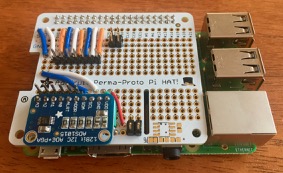
- Schematic of the connections (PDF). Links to details on the hardware:
Connections for the DHT22 sensors to the RJ45 bus
The DHT22 has 4 pins but pin 3 is not used.

Each one requires a connection to power and ground plus a unique GPIO port on the Raspberry Pi for data. The RJ45/CAT5 has 8 wires. Two are reserved for power and earth so that leaves 6 for sensors. The RJ45 terminal blocks have a different wire colouring to the CAT5 cable. Here's how they are allocated:
| RJ45 Pin number | CAT5 wire colour | RJ45 terminal block wire colour | GPIO# or power assignment | ID on unit |
|---|---|---|---|---|
| 1 | orange/white | grey | 4 | TH1 |
| 2 | orange | orange | 17 | TH2 |
| 3 | green/white | black | 18 | TH3 |
| 4 | blue | red | +3.3V | |
| 5 | blue/white | green | GND | |
| 6 | green | yellow | 27 | TH4 |
| 7 | brown/white | blue | 22 | TH5 |
| 8 | brown | brown | 23 | TH6 |