User Tools
Sidebar
This wiki is not maintained! Do not use this when setting up AuScope experiments!
Table of Contents
Antenna Pointing Solutions
Reduction of observations and producing a model
There are two methods of producing a pointing model for the 12m antennas. There's the 'old' way using octave scripts and the power sensor or the 'new' way using the built-in PCFS pointing routines. The 'new' way is recommended because the Field System no longer uses the pointing model in the antenna controller by default. However it's important to keep the pointing models synchronised between the PCFS and antenna controller because some applications (like spacecraft tracking) still require the model in the controller.
The model parameters are implemented slightly differently in the PCFS and the Controller. Here are some notes on the differences between the internal PCFS model and the model implemented within the controller: Model Param notes. Note the sign change in one of the parameters.
Obtaining a pointing model with the PCFS
It's a good idea to allow about 24h of observing to obtain a new pointing solution. Then some additional time is required (a few hours) to confirm that the new solution is working.
- Start up the field system software as usual and make sure the DBBC is set up in a standard R1/R4 configuration.
- It's probably worth using eRemoteControl for this too and setting up the log monitor so you will be alerted if there's a problem.
- The pointing routine will append (or make) a log file called
/usr2/log/sx.logwhich is later used to make a pointing solution. If this file already exists, consider renaming it so there's a fresh one for the new solution. - Then, in the field system:
proc=point
initp
acquire
- The Field System will then automatically choose a pointing source and determine an offset. It will continue to do this indefinitely for a range of sources. Let it run for 24h.
During the pointing run
Lots of messages are produced from the fivpt (pointing) routine. It's worth watching the output (initially anyway) to check it's making sense:
- Monitoring and plotting pointing data during a pointing run
Ending a pointing run
When you think you have enough data, stop the pointing run in the field system by killing the pointing routines, zeroing the pointing offsets and send the antenna to stow:
kill
azeloff=0d,0d
source=stow
Finding a pointing solution
Open a terminal on the Field System (make sure X11 is being forwarded) then start up the pointing solution GUI:
pdplt &
Load the log file with File → New. To cycle through the plots use the Graph menu or n and p. By default the fit residuals are shown but you can also plot the raw data under the Data menu. Obviously bad data can be flagged by clicking on points. To remove outliers automatically, try the Edit → x-sigma option to remove points more than a specified number of sigma out. After flagging points, you can use the Edit → Reprocess option to re-fit the data. If necessary, do some more flagging and reprocess.
The Edit → Modify Parameters option lets you control how and which parameters are used. The default (params 1 through 8 and number 23 set to 1, the rest 0) seems to work well. Note that parameters 15, 16, 17 and 18 (frequency 2 tilt) have been used at the GSFC 12m to improve the solution. However, it's worth producing a solution using the default parameters too because this can be copied to the controller (which doesn't support the other parameters).
The Statistics menu shows you how good the fit is.
When you are satisfied with the pointing solution:
File -> Save
This will save two new files in /usr2/log. The xtr file contains the data which can be re-loaded and reduced if necessary. The err file contains the new model: look for new_model in the file.
Updating the pointing model
To update the pointing model (which will go into /usr2/control/mdlpo.ctl) use the update command. If the new model is called err2013.043, type
update 2013.043
Then check the new file to see if it's been updated.
To copy the model into the controller, use HMI
Obtaining a pointing model with the Power Sensor
An octave script (fitter.m) is available for reducing scans made using “ramps” in the HMI controller and the “monochanstart.sh” scripts in ~oper/Agilentu2k/. The monochanstart.sh script reads from the power sensor and writes it to a file - usually ~oper/Agilentu2k/sensordata.txt. To use the script, start octave and run fitter from the command line. You will be prompted for a file name and the mjd day and seconds of the scan. The output is the amplitude (in dB), the FWHM and central location (in seconds). To best use this, scans made using a ramp where the nominal position is reached at a defined epoch are recommended as this allows for simple estimation of the pointing offset (fitter central location - ramp epoch)*(ramp rate in degrees/sec). The script is made up of three files - fitter.m, fittererr.m and julday.m and requires the debian packages octave, octave-io and octave-optim to be installed.
Hobart 12m model
Version 2016.135
Taken following the installation of the new cable wrap.
Newly derived coefficients:
  00008  2017  135  00  53  37 0
   90.0000  1 1 1 1 1  1 1 1 0 0  0 0 0 0 0  0 0 0 0 0  0 0 1 0 0  0 0 0 0 0
  -0.7106876969   0.0000000000   0.0228546374   0.0497939363   0.0030318052
  -0.0002992165   0.1175717711   0.0146358637   0.0000000000   0.0000000000
   0.0000000000   0.0000000000   0.0000000000   0.0000000000   0.0000000000
   0.0000000000   0.0000000000   0.0000000000   0.0000000000   0.0000000000
   0.0000000000   0.0000000000   0.0019028779   0.0000000000   0.0000000000
   0.0000000000   0.0000000000   0.0000000000   0.0000000000   0.0000000000
The HMI controller was updated 30/05/17
| FS Coeff | HMI Coef | New FS model |
|---|---|---|
| P1 | G2 | -0.7107 |
| P3 | G3 | 0.0229 |
| P4 | -G1 | 0.0498 |
| P5 | G5 | 0.0030 |
| P6 | -G4 | -0.0003 |
| P7 | G7 | 0.1176 |
| P8 | G8 | 0.0146 |
| P23 | G9 | 0.0019 |
| HMI Coef | Value |
|---|---|
| G1 | -0.0498 |
| G2 | -0.7107 |
| G3 | 0.0229 |
| G4 | 0.0003 |
| G5 | 0.0030 |
| G6 | not used |
| G7 | 0.1176 |
| G8 | 0.0146 |
| G9 | 0.0019 |
Version 2016.235
Taken following re-installation of S/X feed and movement of subreflector to original position.
Newly derived coefficients:
  00007  2016  235  23  14  09 0
   90.0000  1 1 1 1 1  1 1 1 0 0  0 0 0 0 0  0 0 0 0 0  0 0 1 0 0  0 0 0 0 0
  -0.4333212972   0.0000000000   0.0158737078   0.0405583084   0.0002418841
   0.0006486370   0.1193821207   0.0167687163   0.0000000000   0.0000000000
   0.0000000000   0.0000000000   0.0000000000   0.0000000000   0.0000000000
   0.0000000000   0.0000000000   0.0000000000   0.0000000000   0.0000000000
   0.0000000000   0.0000000000   0.0006459429   0.0000000000   0.0000000000
   0.0000000000   0.0000000000   0.0000000000   0.0000000000   0.0000000000
| FS Coeff | HMI Coef | New FS model |
|---|---|---|
| P1 | G2 | -0.4333 |
| P3 | G3 | 0.0159 |
| P4 | -G1 | 0.0406 |
| P5 | G5 | 0.0002 |
| P6 | -G4 | 0.0006 |
| P7 | G7 | 0.1194 |
| P8 | G8 | 0.0168 |
| P23 | G9 | 0.0006 |
| HMI Coef | Value |
|---|---|
| G1 | -0.0406 |
| G2 | -0.4333 |
| G3 | 0.0159 |
| G4 | -0.0006 |
| G5 | 0.0002 |
| G6 | not used |
| G7 | 0.1194 |
| G8 | 0.0168 |
| G9 | 0.0006 |
Field system and HMI have been updated
Temporary HMI model
This is a temporary model applied in HMI during broadband tests with the Callisto system.
Original model:
P1 -0.0335
P2 -0.4380
P3 0.0066
P4 -0.0026
P5 -0.0023
P6 0
P7 0.1538
P8 0.0214
P9 0.0026
Additional offsets are
Az = +2.7 arcmin = 0.045 deg
El = -4.0 arcmin = -0.0667 deg
The DC terms in the pointing model are P2 (Az) and P7 (El), so new model is:
P1 -0.0335
P2 -0.393
P3 0.0066
P4 -0.0026
P5 -0.0023
P6 0
P7 0.08713
P8 0.0214
P9 0.0026
Version 2016.151
2 June 2016
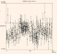
Observations over 24he. Little change to rms before and after
Data:
xEl mean -0.0013
xEl RMS 0.007
El mean -0.015
El RMS 0.008

After solution:
xEl RMS 0.007
El RMS 0.009
Solutions applied err2016.151
Version 4.2
Model updated from observations taken over a few days around 2014/205. Slight dependance on Elevation offset with Azimuth removed. Otherwise looks good.
Version 4.1
Slight offset in elevation. Model updated from observations on 2013/323
Version 4.0
Taken using PCFS on 2013 day 043/044. Coefficients used during pointing:
*  0 0 0 0 0 0 0
*   90.0   1 1 1 1 1  1 1 1 0 0  0 0 0 0 0  0 0 0 0 0  0 0 0 0 0  0 0 0 0 1
*  -0.4263 0.0 0.0048 0.0363 -0.0004
*  -0.0026 0.1906 0.0250 0.0 0.0
*  0.0 0.0 0.0 0.0 0.0
*  0.0 0.0 0.0 0.0 0.0
*  0.0 0.0 0.0 0.0 0.0
*  0.0 0.0 -0.0014
Newly derived coefficients:
  00002  2013  044  23  30  55 0
   90.0000  1 1 1 1 1  1 1 1 0 0  0 0 0 0 0  0 0 0 0 0  0 0 1 0 0  0 0 0 0 0
  -0.4380196333   0.0000000000   0.0065650782   0.0334785432  -0.0023106572
   0.0025938717   0.1538095325   0.0214055236   0.0000000000   0.0000000000
   0.0000000000   0.0000000000   0.0000000000   0.0000000000   0.0000000000
   0.0000000000   0.0000000000   0.0000000000   0.0000000000   0.0000000000
   0.0000000000   0.0000000000   0.0025560106   0.0000000000   0.0000000000
   0.0000000000   0.0000000000   0.0000000000   0.0000000000   0.0000000000
In HMI these are translated to:
| Coeff | Old model | New model |
|---|---|---|
| P1 | -0.0363 | -0.0335 |
| P2 | -0.4263 | -0.4380 |
| P3 | 0.0048 | 0.0066 |
| P4 | -0.0026 | -0.0026 |
| P5 | -0.0004 | -0.0023 |
| P6 | not used | |
| P7 | 0.1906 | 0.1538 |
| P8 | 0.0250 | 0.0214 |
| P9 | -0.0014 | 0.00255 |
Field system and HMI have been updated
Version 3.4
30 June 2011
Some pointing checks made prior to IVS experiments in the last month indicated potential pointing problems. A series of pointing observations were made on 29/6/2011. The new model parameters are included below and the data file is included here.
P1 = -0.0004
P2 = -0.4131
P3 = 0.0230
P4 = 0.0050
P5 = -0.0139
P7 = 0.1998
P8 = 0.0000
P9 = 0.0029
Version 3.3
17 Feb 2011
Investigation of the elevation offset problem suggests a physical (encoder) cause.
Brett made an inspection of the elevation encoder mount on Feb 16 afternoon. He found that the bolts attaching the aluminium encoder bracket to the antenna were loose and so he tightened them up a little. We’re inclined to see if this has fixed the problem before attempting to remove the encoder and coupling to check the coupling to encoder shaft join.
A pointing check after this showed a 0.05 deg offset
New data show a mean El offset of 0.155 deg, which appears to be a DC offset. No significal cross-El offset seen.
New P7 = 0.1667 + 0.05 = 0.2167
Version 3.2
18 Jan 2011
An offset in Elevation has been detected, which appears to have started between Nov 4 and 8 for no known reason.
New data show a mean El offset of 0.155 deg, which appears to be a DC offset. No significal cross-El offset seen.
New P7 = 0.0117 + 0.155 = 0.1667
Version 3.1
3 September 2010
After new feed installation, some additional pointing observations were made. There seems to be a global offset, mostly in Elevation that's constant in all tested Az and El coordinates.
Mean offsets are:
cross El = -0.0033
El = 0.0784
DC offsets in Elevation are in P7 and in cross-El is in P1. So parameters to change are:
P1 = -0.0527 -0.0033 = -0.056
P7 = -0.0637 + 0.0784 = 0.0117
Data used for the new solution
Version 3.0
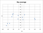
Based on observations from 19 March 2010 and the Version 1 input model. i.e note, this is a re-analysis of data taken for Version 2, but only using the new data. The following offsets were measured: hobart_pointing_v2.0.xlsx. The new solution was calculated using a perl script that uses the same fitting method as used for V2 and V1. Solution is
P1 = -0.05271
P2 = -0.40045
P3 = 0.01455
P4 = 0.00099
P5 = -0.00729
P7 = -0.06368
P8 = 0.01494
P9 = -0.00291
Comparison with previous model:
Stats with V2.0 solution
XEl offsets: Mean = -0.010969, RMS = 0.038104
El offsets: Mean = 0.060875, RMS = 0.056499
Stats with new solution
XEl offsets: Mean = 0.001096, RMS = 0.012678
El offsets: Mean = -0.000078, RMS = 0.007121
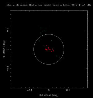
Scatter plot of offsets (before vs after):
Version 2.0
Based on more observations and used for the fringe-check on day 110. There still appear to be significant residuals but the solutions are OK for fringe-checking.
Things to check:
- Opacity correction implementation
- Fitting algorithm
- Procedure for confirming solutions
Solution (based on all observations to date) used was:
P1 = -0.071
P2 = -0.376
P3 = 0.023
P4 = -0.013
P5 = -0.016
P7 = -0.096
P8 = 0.032
P9 = -0.004
Version 1.0
Based on 13 individual observations only, so more work is required and testing of this model is needed. The spreadsheet containing observations and model fits is attached: hobart_pointing_v1.0.xlsx Pointing model coefficients used during the pointing observations:
P1 = -0.36
P2 = 0
P3 = 0
P4 = 0.007
P5 = 0.0082
P6 = 0
P7 = -0.1760
P8 = 0
P9 = 0
Components P4 and P5 are the tilt components in Az and El as provided by Patriot. P1 and P5 are cross-el and El DC offsets (guessed by Jim L). Note P6 is not used so it is effectively a 8 component model. Solutions were obtained with P4 and P5 fixed as well as letting all vary. Of the two, the less constrained model gave the better fit and differences between the old and new model were less, so this has been chosen as Version 1.0. Tests will need to be made to confirm the model is effective and to increase the number of samples on the sky. The Solution is:
P1 = -0.495
P2 = 0.030
P3 = 0.220
P4 = -0.025
P5 = -0.036
P6 = 0
P7 = 0.044
P8 = -0.175
P9 = -0.008
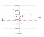
Solutions (offsets from model) before and after:
Katherine 12m model
Version 2016.151
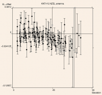
Observations over 24h following recent maser maintenance. Little change to rms before and after
Data:
xEl mean 0.0027
xEl RMS 0.007
El mean -0.0118
El RMS 0.0118

After solution:
xEl RMS 0.0126
El RMS 0.013
Solutions applied err2016.151
Version 1.0
Following a series of observations resulting in 23 offset measurements on 7 & 8 June 2011, a new model was determined. Model used during observations:
P1 = -0.155
P2 = 0.0
P3 = 0.0
P4 = 0.0
P5 = 0.0
P6 = 0.0
P7 = 0.32
P8 = 0.0
P9 = 0.0
New model:
P1 = -0.0436
P2 = -0.2739
P3 = 0.021
P4 = 0.0124
P5 = -0.0184
P6 = 0.0
P7 = 0.3822
P8 = -0.0193
P9 = -0.0015
No change to encoder offsets in the controller.
This model was loaded on June 8 2011
Statistics
Stats with old solution
XEl offsets: Mean = -0.077, RMS = 0.064
El offsets: Mean = 0.045, RMS = 0.02
Stats with new solution
XEl offsets: Mean = 0.0004, RMS = 0.007
El offsets: Mean = 0.0008, RMS = 0.016
Data and calculations
Yarragadee 12m model
Version 2016.151
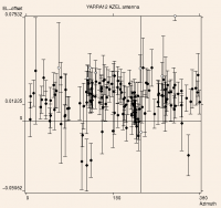
Observations over 24h following recent maser maintenance. Little change to rms before and after
Data:
xEl mean -0.0006
xEl RMS 0.011
El mean 0.015
El RMS 0.008

After solution:
xEl RMS 0.012
El RMS 0.010
Solutions applied err2016.151
This solution was put into HMI on 22 June 2016, ~23:45 UT (day 174). Parameters are:
G1 -0.0105
G2 -0.0070
G3  0.0180
G4  0.0094
G5 -0.0024
G7  0.2059
G8  0.0158
G9  0.0007
Note that these were initially put in to HMI on June 20 but the sign for G4 was wrong. Not sure if that had a significant impact or not.
Also updated HMI (on day 175, 00 UT) with revised station coordinates. Only sig change was to elevation which was 50m too low.
Lat, Long, Elevation:
Before: -29.0465, 115.3467, 200.0
After: -29.0469, 115.3465, 250.48
Version 1.5
Model v1.4:
P1  -0.0243
P2  0.0036
P3 0.0165
P4 0.0110
P5 -0.0074
P6 0
P7 0.9540
P8 -0.0580
P9 0.0021
Elevation encoder offset (1.20.21) is currently -50067 = -5.0067 deg. Manual says this is ADDED to the encoder outputs.
So the Real el encoder angle is indicated minus 5.0067 deg.
The pointing model has an additional 0.954 deg correction. In this case though it means that the demanded position should be 0.954 deg higher than indicated. In other words the new Encoder offset should be -5.0067 - 0.9540 = -5.9607. So new encoder parameter should be -59607
Current low soft limit 20.22 = 60000 = 6.0 deg
Current high soft limit 20.23 = 885000 = 88.5 deg
Notes on what was done to update the model:
Elevation Encoder offset.
1. The current Elevation encoder offset is −50067 = −5.0067 deg. It should should be −59607 as we’ve accumulated another 0.954 degrees since it was last changed. 2. This change must be made at the controller in the pedestal on the Elevation encoder module:
a. Put the controller in STANDBY
b. Navigate to parameter 20.21 which should be the Elevation encoder offset and should read −50067.
c. Press the “M” button to enter the editing mode and change the number to −59607 using the elliptical button with the arrows on it
d. Press “M: again to exit edit mode. The upper display (parameter number) should be flashing. You’re now in “temporary parameter” mode
e. Press “M” again to return to Status mode
3. You now need to save the above change. Navigate to parameter 0.00 on the El controller module and edit it as you did in step 2, except make it’s value 1000. 4. After editing and saving, cycle the power to the controller, then go back to 20.21 and make sure it still has the new value.
Lower Elevation Soft Limit
The procedure for changing this is the same as above except you’re changing parameter 20.22 which is currently set to 60000 (6.0 deg) to 50000 (5.0 deg).
New model is
Model v1.5:
P1  -0.0243
P2  0.0036
P3 0.0165
P4 0.0110
P5 -0.0074
P6 0
P7 0.0
P8 -0.0580
P9 0.0021
Version 1.4
Observations on June 16 prior to R4487. Further offset of 0.0375 added to El. P7 now 0.774
Version 1.4
Observations on June 8. Further offset of 0.0614 added to El. P7 now 0.7365
Version 1.3
Observations on May 23:
El offset = 0.19
xEl offset = 0
No correction applied to model.
Observations on May 25, prior to fringe check:
El offset = 0.215
xEl offset = 0
DC offsets in Elevation are in P7. So parameters to change are:
P7 = 0.4601 + 0.215 = 0.6751
Model updated 25 May 2011, 02:12 UT.
Version 1.2
Observations on May 16, following work by Brett and Randall on the 13th (see ops log) showed a new DC offset in El no offset in xEl.
El offset = 0.11
DC offsets in Elevation are in P7. So parameters to change are:
P7 = 0.3501 + 0.11 = 0.4601
Model updated 16 May 2011.
Version 1.1
Observations on May 3 and 4 showed a new DC offset in El and a small offset in xEl.
El offset = 0.35
xEl offset = -0.025
DC offsets in Elevation are in P7 and in cross-El is in P1. So parameters to change are:
P1 = 0.0007 -0.025 = -0.0243
P7 = 0.0001 + 0.35 = 0.3501
Model updated 5 May 2011.
Version 1.0
Following a series of observations resulting in 50 offset measurements, a new model was determined:
P1 = 0.0007
P2 = 0.0036
P3 = 0.0165
P4 = 0.0110
P5 = -0.0074
P6 = 0.0
P7 = 0.0001
P8 = -0.0580
P9 = 00021
No change to encoder offsets in the controller.
This model was loaded on April 11 2011, 03:30 UT.
Statistics
Stats with old solution
XEl offsets: Mean = 0.010638, RMS = 0.009923
El offsets: Mean = -0.068184, RMS = 0.015451
Stats with new solution
XEl offsets: Mean = -0.000139, RMS = 0.009912
El offsets: Mean = -0.000236, RMS = 0.014916
Data and calculations
Initial models
Initial pointing offsets (Stas) were xEL=0.24, El=0.4.
April 6:
Changed P1=0.24
P7 still 0.4
All others kept to 0
Also changed site elevation to 200m from 100m
April 7:
Based on limited pointing data and some follow-up checks, the following model was used:
P1 = -0.0058
P2 = 0.0
P3 = 0.0142
P4 = 0.0114
P5 = -0.0081
P6 = 0.0
P7 = 0.05
P8 = -0.0265
P9 = -0.001
As well as this, encoder offsets were loaded into the controller EL module (20.21) and Az master module (20.21) as follows:
El 20.21 = -50067 (i.e. -5.0067 deg)
Az 20.21 = -1141  (i.e. -0.1141 deg)

